Access to on-board and off-board devices is memory-mapped. The address range dedicated to VME-access is subdivided into several segments to accommodate all kinds of VME-cycle types, since the transputer is only capable of 32-bits read cycles and 32-bits or 8-bits write cycles.
All write cycles in VME are performed in a pipelined fashion, meaning that the VME-interface independently performs the cycle after the address and data have been received from the transputer. The transputer can continue processing locally, while the VME-interface completes the VME-cycle.
Read cycles in VME are not performed in such a pipelined fashion unless the so called Postfetch Mode is used (see section 3.8).
The rest of this chapter describes how to access the VME-bus. The tables in Appendix A give an overview of the memory map of the 2TP-VME transputers.
In the case of VME access the transputer address range is subdivided into 4 main 1-GByte segments accommodating the different VME address/data area types. Table 1 summarizes these VME address/data area types.
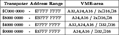
Table 1: VME address/data area types if in the corresponding transputer
address range a VME-area is selected (2xD16 = a longword transputer access
results in two D16 VME-cycles in consecutive VME word-locations).
Two of the 1-GByte segments are subdivided into smaller segments of 16 MByte as detailed in the memory map in Appendix A. Each segment has an associated programmable Address Modifier Register, the contents of which will be enabled onto the VME AM-lines when a VME-access is performed in the corresponding transputer memory segment (see section 5 on Address Modifier Registers).