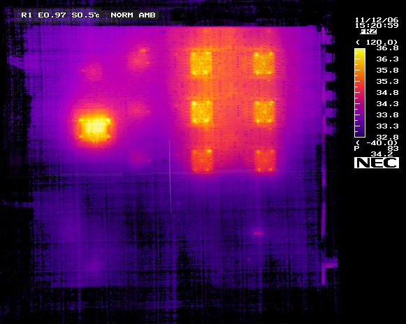
MROD-X Solder Side Thermal Picture
| |
|
| FPGA: |
Degrees Centigrade |
| Channel 1-A |
42 |
| Channel 1-B |
45 |
| Channel 2-A |
43 |
| Channel 2-B |
45 |
| Channel 3-A |
40 |
| Channel 3-B |
41 |
| MROD-Out |
56 |