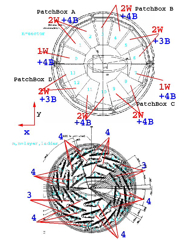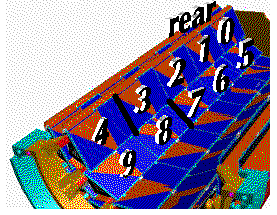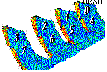
Indicated is the order of the cabling for the ladders: first output cable
modules 0-3, the second 4-7 etc. (N.B i.e. not the module
numbering)
Indicated is the order of cabling for the wheels: 0-3 for the first output
cable, then 4-7
etc.
Items:
They go to PatchBox C, since that one seems to be rather empty.
Wires of (1) and (2) are included in the combo cable. In the table below the number of outputs is calculated per patchbox under the assumption of 20 Combo cable inputs per SC patchbox board and barrel/wheel cables kept apart. SC output cable and connector: standard cable plus D connector; same type on all patchbox boards.
From 4 ladders 5 COMBO cables each (so 20 in total) are fed into a link patchbox board. For the wheels that number is 16 at maximum per patchbox board. The output is on RJ-45 cables and connectors with 4 link signals each (signal1=dummy1, signal2=analog2 etc; pin 9 and 10 are ground). Cables of barrel ladders on patchbox A and B go to ADC crate 1, those on patchbox C and D to ADC crate 2. All wheel cables go to ADC crate 3.
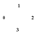
Four Radiation Monitor cables of the rear detectors go to patchbox C, flange
hole nr. 5: R0,R1,R2,R3. They share the zipper with the MVD-SC STP
cables. The four cables of the forward detectors go to patchbox D, flange
hole nr. 7: F0,F1,F2,F3. Here we assume the following numbering convention
for both the forward and rear monitors, as seen from the rear (RCAL):

| PatchBox | Ladder/Wheel/Other | inputs | LINK outputs | SC outputs | Temp sensor subdivision |
| 1=A | L | 8*5 | 40 (20 +20) | 12 (8 + 4) | 8 hybrid + 4 det. sensors 0.0 |
| ,, | W | 3*4 | 12 | 4 | 4 det. sensors sector 0 |
| 2=B | L | 7*5 | 35 (20 + 15) | 11 (8 + 3) | 7 hybrid + 4 det. sensors 2.4 |
| ,, | W | 4*4 | 16 | 8 |
4 hybr. sensors sector 3 +
4 det. sensors sector 4 |
| 3=C | L | 8*5 | 40 (20 + 20) | 8 (4 + 4) | 8 hybrid sensors |
| ,, | W | 3*4 | 12 | 0 | - |
| O | 5 | na | 5 | see SC cabling item 3 | |
| 4=D | L | 7*5 | 35 (20 + 15) | 11 (8 + 3) | 7 hybrid + 4 det. sensors 0.3 |
| ,, | W | 4*4 | 16 | 8 |
4 det. sensors sector 13 +
4 hybr. sensors sector 10 |
In which order the outputs appear on each board depends on the precise ordering of the cabling: this is trivial for the wheels but not for the ladders. For e.g. patchbox 1=A the ladder order could be according to layer order(A): 0.0, 1.0, 1.1, 1.2, 2.0, 2.1, 2.2, 2.3 or by geographical cable coherence (B): 0.0, 1.0, 2.0, 2.1, 1.1, 1.2, 2.2, 2.3. The ladder ordering for the patchboxes used below is (B).
| Patchbox | flange hole nr | ladders |
sectors |
| 1=A | 0 | 0.0,1.0,2.0,2.1 | 0 |
| 1 | 1.1,1.2,2.2,2.3 | 1,2 | |
| 2=B | 2 | 0.1,1.3,2.4,2.5 | 3,4 |
| 3 | 1.4,2.6,2.7 | 5,6 | |
| 3=C | 4 | 1.5,1.6,2.8,2.9 | 7 |
| 5 | 0.2,1.7,2.10,2.11 | 8,9 | |
| 4=D | 6 | 0.3,1.8,2.12,2.13 | 10,11 |
| 7 | 1.9,2.14,2.15 | 12,13 |
For more info about cable routing see the index of the postscript drawings: the Cable Roll-Out in the MVD volume (zmm004.ps) and the Cable Layout at the Rear Barrel Flange (zmm002.ps).
The MVD-SC cables go to PatchBox C through flange hole nr. 5. In addition there are 8 STP cables from the hardstop switches in the bundle.
Below the SC output ordering for all 4 patchboxes:
| board | PatchBox 1=A | PatchBox 2=B | PatchBox 3=C | PatchBox 4=D |
| 1 | hybr sensor 0.0, mod 0 | hybr sensor 0.1 | hybr sensor 1.5 | hybr sensor 0.3, mod 0 |
| hybr sensor 0.0, mod 1 | hybr sensor 1.3 | hybr sensor 1.6 | hybr sensor 0.3, mod 1 | |
| hybr sensor 0.0, mod 2 | hybr sensor 2.4, mod 0 | hybr sensor 2.8 | hybr sensor 0.3, mod 2 | |
| hybr sensor 0.0, mod 3 | hybr sensor 2.4, mod 1 | hybr sensor 2.9 | hybr sensor 0.3, mod 3 | |
| hybr sensor 0.0, mod 4 | hybr sensor 2.4, mod 2 | - | hybr sensor 0.3, mod 4 | |
| hybr sensor 1.0 | hybr sensor 2.4, mod 3 | - | hybr sensor 1.8 | |
| hybr sensor 2.0 | hybr sensor 2.4, mod 4 | - | hybr sensor 2.12 | |
| hybr sensor 2.1 | hybr sensor 2.5 | - | hybr sensor 2.13 | |
| 2 | hybr sensor 1.1 | hybr sensor 1.4 | hybr sensor 0.2 | hybr sensor 1.9 |
| hybr sensor 1.2 | hybr sensor 2.6 | hybr sensor 1.7 | hybr sensor 2.14 | |
| hybr sensor 2.2 | hybr sensor 2.7 | hybr sensor 2.10 | hybr sensor 2.15 | |
| hybr sensor 2.3 | - | hybr sensor 2.11 | - | |
| 3 | hybr sensor sector 0, det 0 | hybr sensor sector 3, det 0 | - | hybr sensor sector 10, det 0 |
| hybr sensor sector 0, det 1 | hybr sensor sector 3, det 1 | - | hybr sensor sector 10, det 1 | |
| hybr sensor sector 0, det 2 | hybr sensor sector 3, det 2 | - | hybr sensor sector 10, det 2 | |
| hybr sensor sector 0, det 3 | hybr sensor sector 3, det 3 | - | hybr sensor sector 10, det 3 | |
| - | hybr sensor sector 4, det 0 | - | hybr sensor sector 13, det 0 | |
| - | hybr sensor sector 4, det 1 | - | hybr sensor sector 13, det 1 | |
| - | hybr sensor sector 4, det 2 | - | hybr sensor sector 13, det 2 | |
| - | hybr sensor sector 4, det 3 | - | hybr sensor sector 13, det 3 |
Luc Jansen has made a detailed scheme for the wiring of the SC modules.
Last changed on: Mon, 12-4-2001 by Leo Wiggers