| Subject: |
STRUCTURAL ANALYSIS OF THE
INSTALLATION RAIL FOR THE
TWO DETECTORS
|
| Group: | Engineering dept. NIKHEF |
| Date: | may 2004 |
| Prepared by: | M.J. Kraan |
| Checked by: | M. Doets |
|
Abstract:
The structural verification of the Installation Rail for the two detectors is the subject of this document.
Purpose of these calculations is to investigate stress and stability of this device.
Numerical analysis was performed with the IDEAS TM finite element analysis software.
Introduction
For installation of the two detectors a Installation Rail is designed.
Figures below shows this device with one of the two detectors in front of the vacuum vessel.
Design of the Installation Rail
The rail consist of two stainless steel translation bearings mounted on a
aluminium frame. This frame is bolted together. The whole assembly will be
mounted to the vacuum vessel and the stand.
Drawings in PDF Format
Operational conditions
The load of the lifting device is determined by the weight of a detector.
With a weight of each detector of 2000 N, the load is devided over the two bearings by:
F1 = 250 N
F2 = 750 N
|

|
Material data:
This device will be made from Stainless steel (bearing) and Aluminium (frame)
| STAINLESS STEEL |
| Tensile strength | Rm [MPa] | min. | 580 |
| Yield strength | Rp 0.2% [MPa] | min. | 290 |
| Young's modulus | E [GPa] | min. | 200 |
| Density | [g/cm3] | . | 8.0 |
| Poisons ratio | . | . | 0.30 |
|
| ALUMINIUM |
| Tensile strength | Rm [MPa] | min. | 180 |
| Yield strength | Rp 0.2% [MPa] | min. | 80 |
| Young's modulus | E [GPa] | min. | 700 |
| Density | [g/cm3] | . | 2.69 |
| Poisons ratio | . | . | 0.30 |
|
FEA:
A finite element analysis has been done to verify that the stresses are below the Yield strength.
The finite element analysis is done with the finite element analysis module of Ideas.
The model is build up with 3D Solid parabolic tetrahedron
elements. to simulate the 'worse case scenario', the detector is 'placed' at the end of the translation bearing.
A buckling analysis is presented as the stresses in some sections are compressive.
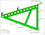
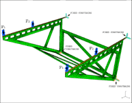
Two models are made, first: only the vertical plate with constrains at the places where the bolds are
and second: the whole structure as one part.
| Finite Element Mesh |
| vertical plate | one part |
 |
 |
| Mesh types: |
3D Solid parabolic tetrahedron
|
| Load type: | LOAD on Surface |
| Weight 1 detector: | 2000 N |
| Load Amplitude: | F1=250 N / F2=750 N
|
| Type of Solution: | Linear Statics |
| Units: | Length [mm]; Force [N]; Stress/Pressure [Mpa] |
|
|