Setup of the experiment
The MuonLab instrument basically consists of two scintillation detectors connected to a signal analyzer and interfaced to a computer.
Schematically:
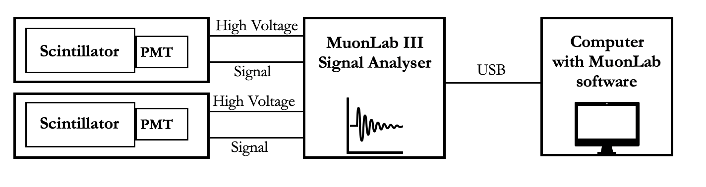
A detector comprises the scintillator material, which is connected to a photo-multiplier tube (PMT) and is completely enclosed in a protective cover. The short light flashes generated by muons traversing the scintillator are converted into electrical pulses by a Hamamatsu 6094 photomultiplier (PMT).
The electronics of the signal analyzer is based on a FPGA hardware circuit and a VHDL firmware program, saved in an EPROM. The device has a time resolution of 0.5 nanosecond. Control and read-out can be realized via an USB connection to a computer.
A dedicated user interface in the computer has been implemented by a software program. The user interface allows the students to set the parameters for a particular run and to graphically display, analyze and store the measurements.
For a muon lifetime measurement in principle only one scintillation detector is sufficient. A time counter is started by a trigger generated by the pulse from the incoming muon and is stopped by the trigger from the pulse generated by the electron that is produced in the decay of the muon.
In a configuration with two scintillation detectors, vertically separated by a few meters, the instrument can measure the time difference between the triggers of pulses in the two detectors, generated by the same muon. From the measurement the velocity of muons can be calculated.
In a configuration with two scintillation detectors placed next to each other the instrument can measure coincidences, originating from air showers, between pulses in both detectors. The gate for coincidences is set by firmware to 100 ns, making the probability for random coincidences very small. After placing an amount of lead above the detectors, effects of the generation of a shower of secondary particles in the lead material can be observed. By placing varying numbers of lead plates it is possible to show that the number of generated secondary particles increases with the thickness of the layer of material.
With the two detectors set in the coincidence mode, the instrument also offers the possibility to measure the amplitude of the signal by sampling the analog pulse with a 200 MHz analog to digital converter (ADC) in the analyzer box.
Preparation of the instrument for measurements has to be performed by first connecting the two detectors to the signal analyzer by means of a BNC cable for the signal and a DIN cable for the PMT power and next to connect the signal analyzer to the computer by means of a USB cable. Power has to be provided by the use of a 12 Volt DC adapter connected to the 220 V AC main voltage.