
MROD-X
| |
|

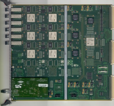
The MROD-X will make use of Xilinx Virtex-II Pro FPGAs. These FPGAs contain RocketIO and PowerPC building blocks. With the use of RocketIO, data can be transported from one FPGA to the other, simple and fast.
Virtual tour. MROD-X PCB pictures.
Reset Topology
SHARC Links that can be used for Data transport from MROD-In to MROD-Out
SHARC Links that can be used for Communication between the SHARC processors
FPGA and Configuration PROM JTAG Chain
SHARC JTAG chain (used by the Visual DSP Emulator)
Power Supply Block diagram
Clock distribution
Test Modes
MROD-X-In (Version 1.8) Programmers Manual (November 23, 2017).
MROD-X-Out (Version 1.10) Programmers Manual (November 30, 2015).
MORD-S2 Redmine Pages
EDMS MROD-X Pages
MROD
PRR documents
Production Readiness Review, November 2, 2005. Electronic design
details / Prototype issues (ppt), (pdf). Or follow this
link to the official
ATLAS Agenda page.
Intermediate Design Review, November 12, 2003. Hardware Implementation (ppt), (pdf). Or follow this
link to the official
ATLAS Agenda page.
The ATLAS page at
the
Radboud Univeristy Nijmegen
The predecessor MROD-1
Preparatory Design Studies MROD-X, February 24,
2004. Slides (ppt),
(pdf).
Or follow
this link to the official ATLAS
Agenda page.
TTC system (RD12 at CERN)
TTC Interface Module (TIM)
S-LINK homepage at
CERN
ATLAS Webcam
at UX15
October 25, 2004:
Schematics frozen, layout started
January 27, 2005:
Layout finished
March 11, 2005:
PCBs received, Assembly started
April 13, 2005:
Two assembled PCBs received, tests started
June 28, 2005:
First MROD-X module succesfully took data in the Cosimic-Ray test stand at NIKHEF in MROD-1 mode
September 12, 2005:
After thorough tests and Event-Rate measurements the MROD-X module now takes data in the Cosimic-Ray test stand at NIKHEF in MROD-X2 mode (using the Rocket-IOs).
November 2, 2005:
PRR was held at CERN
February 9, 2006:
The frequency of the MROD-In and Out parts have been upgraded to 50 MHz.
Temperature tests (0..70 oC) were successful.
Minor changes were made to the PCB layout.October 18, 2006:
15 Pre-Production series modules arrive at Nikhef. October 19, 2006:
First Pre-Production series module passes all software tests.
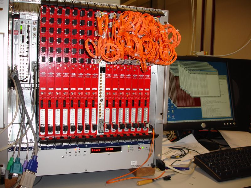
November 30, 2006:
A fully loaded crate with 15 MROD-X modules runs duration tests without problems.
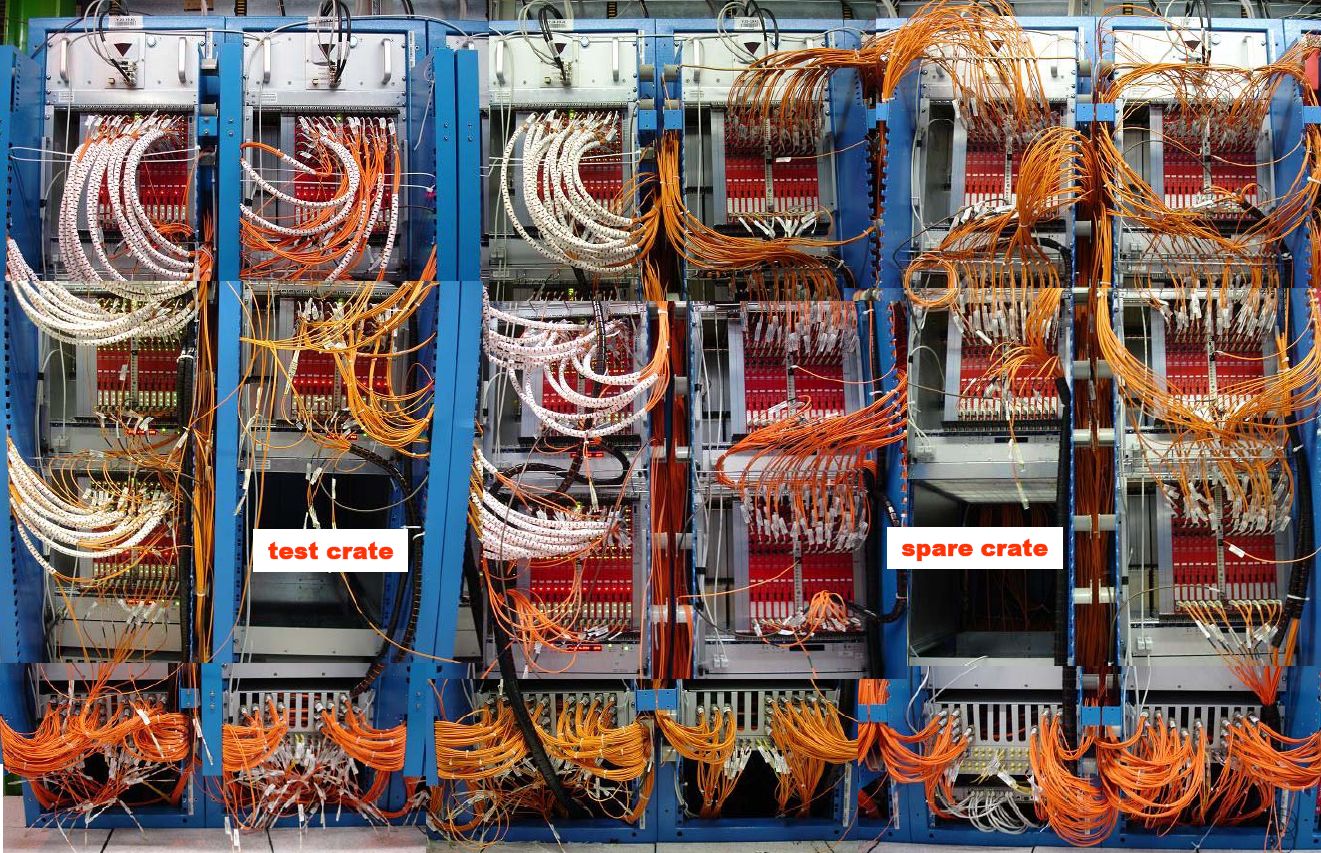
March 25, 2008:
An assembled picture of the MROD system in USA15.
November 9, 2011:
Updated MROD-X-In. Now Version 1.6 due to an update of the Tetris register depth (was 16 rows and is now 32 rows deep)
January 31, 2012:
Updated link to KUN (was http://www.hef.kun.nl/atlas/)