
GOL Test
|
|
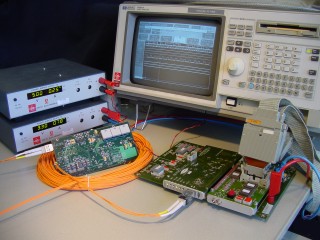
The purpose of this test is to build a Front End link between the CSM to the MROD.
A GOL ASIC is used as a transmitter because the transmitter should be radiation hard. For initial testing, a GOL is mounted on a GOL Test Board. The FPGA on this board can be programmed to send a few events to the MROD when a button is pushed. More about this in the GOL-Test Manual (Version 1.1) (December 19, 2002) (version 1.0 is also available here). The GOL will be used in Gbit Ethernet mode clocked on 25.0000 MHz (32 bit rate).
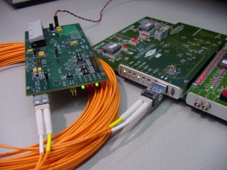
For testing the optical transmission will be done by an Infineon
V23818-K305 optical transceiver (Rx part is not used).
This optical transceiver is not Radiation Hard and should be replaced
by a Radiation Hard device when implemented in the final design.
The data is received on a GOLA board, which is basically a modified
HOLA
S-Link board. The difference is that a slower clock rate, optical transceiver
and Gbit Ethernet transceiver are used. The GOLA board contains a TLK1501
Gbit Ethernet transceiver, which will be clocked at 50.0000 MHz (16 bit
rate). The S-Link signals on the connector of the GOLA board are put into
a state, such that the ROMB (the MROD) is thinking that a working S-Link
is mounted. Read more in the GOLA-Manual
(August 27, 2002).
Note that the GOLA is not an S-Link implementation since it
lacks the S-Link initialization and test features!
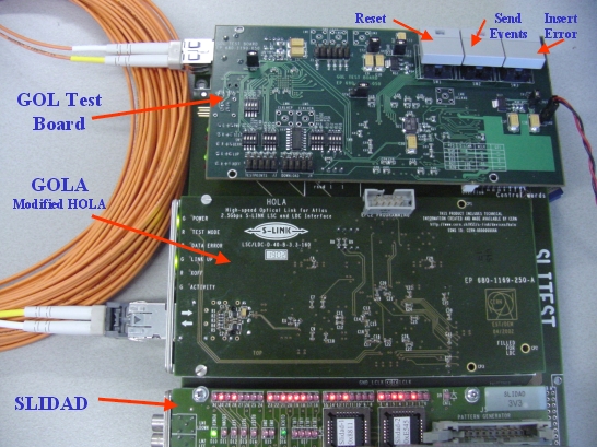
The event data that is send by the GOL when the "Send Events" Push Button is pressed is transferred to the GOLA. The GOLA is mounted on a SLITEST and its output data is verified with a SLIDAD and a logic analyzer.
The physical layer of the link between the GOL and the TLK1501 is based on the IEEE std. 802.3. Chapter 36 of this standard handles the 8/10B coding.
There are two kinds of IDLE characters. /I1/ corrects the running disparity (- to + or + to -) while /I2/ preserves the current running disparity (- to - or + to +). Possible IDLE sequences are drawn here. This is a picture of the IDLE-ing GOL output (GOL in 32-bit Ethernet mode @ 50MHz input clock).
There are two important features about the IDLE string.Here is a proposal for operating the GOL to TLK1501 link on the physical level. This scheme assures proper code group re-alignment whenever synchronization is lost at the receiving side by putting IDLEs into the stream. Also the scheme makes link error checking possible and fits the bandwidth requirements for the 18-TDC readout for the MDT chambers.
- The amount of serial zeros and ones is exactly the same (mind the Runing Disparity rules in chapter 36.2.4.4 of IEEE std. 802.3).
- When data was serialized, the byte boundary that was associated with the parallel data was lost in the serialisation of the data. The IDLE code group <K28.5> has a "Comma" Character that is needed for byte alignment.
The proposal (using a CRC-32) is simulated and verified.Here is the VHDL code for the CRC-32 generator.