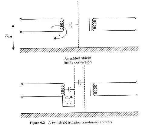
The transformers and associated circuits that are described in this section can be single-phase or three-phase. The single-phase circuit is used as an example because it is simpler to draw. The single shield is shown in Figure 9.1.
 This
transformer is ideally mounted on a ground plane. The single shield is internally
connected to the transformer frame. When the transformer is mounted, the
shield is connected. The primary and secondary conductors are carried in
conduit. The conduit bonds to the transformer frame and is considered a part
of the equipment grounding system.
This
transformer is ideally mounted on a ground plane. The single shield is internally
connected to the transformer frame. When the transformer is mounted, the
shield is connected. The primary and secondary conductors are carried in
conduit. The conduit bonds to the transformer frame and is considered a part
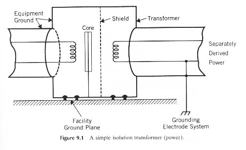
of the equipment grounding system.Transformer action involves the difference signal between the power conductors. There can also be a common-mode signal (interference) on the primary transmission line. The shield in Figure 9.1 reflects any common- mode signals and stops them from coupling to the secondary circuits. Without the shield, capacitance couples common-mode signals directly from the primary to the secondary circuits. In a typical isolation transformer the leakage capacitance out of the shield is about 5 pF. With a shield, most of the common-mode current returns inside the primary conduit and never sees the secondary circuits.
Some of the common-mode current flows in coils of the primary .This current flow appears in the secondary by transformer action. To limit this effect, a second shield can be added to the transformer. This shield is internally connected to one side of the primary coil. Common-mode current now flows between the shields not in the coils of the primary. This added shield is shown in Figure 9.2.